Sealing/Isolating Gaskets and Flange Isolation Kits
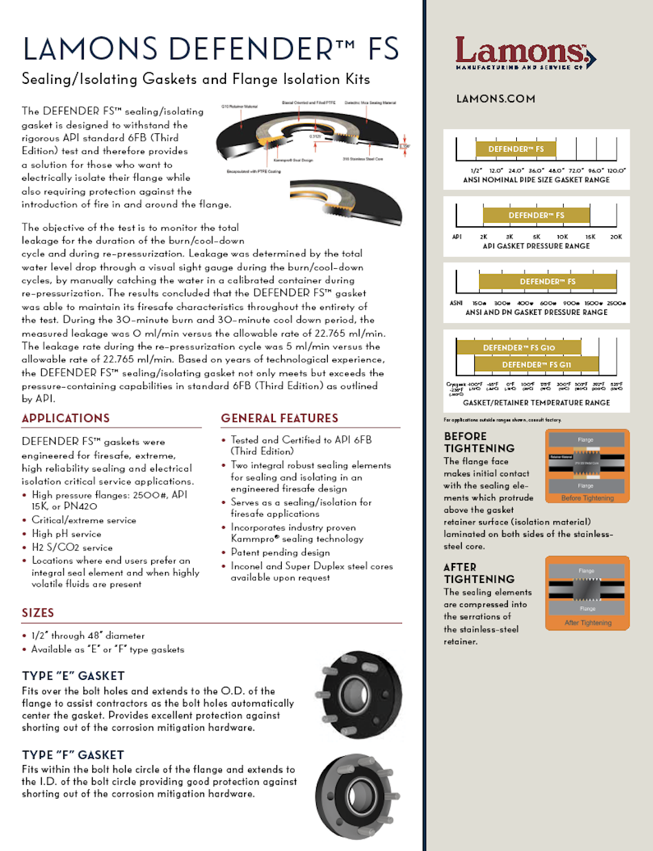
The DEFENDER FS™ sealing/isolating gasket is designed to withstand the rigorous API standard 6FB (Third Edition) test and therefore provides a solution for those who want to electrically isolate their flange while also requiring protection against the introduction of fire in and around the flange.
The objective of the test is to monitor the total leakage for the duration of the burn/cool-down cycle and during re-pressurization. Leakage was determined by the total water level drop through a visual sight gauge during the burn/cool-down cycles, by manually catching the water in a calibrated container during re-pressurization. The results concluded that the DEFENDER FS™ gasket was able to maintain its firesafe characteristics throughout the entirety of the test. During the 30-minute burn and 30-minute cool down period, the measured leakage was 0 ml/min versus the allowable rate of 22.765 ml/min. The leakage rate during the re-pressurization cycle was 5 ml/min versus the allowable rate of 22.765 ml/min. Based on years of technological experience, the DEFENDER FS™ sealing/isolating gasket not only meets but exceeds the pressure-containing capabilities in standard 6FB (Third Edition) as outlined by API.
Applications
DEFENDER FS™ gaskets were engineered for firesafe, extreme, high reliability sealing and electrical isolation critical service applications.
- High pressure flanges: 2500#, API 15K, or PN420
- Critical/extreme service
- High pH service
- H2 S/CO2 service
- Locations where end users prefer an integral seal element and when highly volatile fluids are present
General Features
- Tested and Certified to API 6FB (Third Edition)
- Two integral robust sealing elements for sealing and isolating in an engineered firesafe design
- Serves as a sealing/isolation for firesafe applications
- Incorporates industry proven Kammpro® sealing technology
- Patent pending design
- Inconel and Super Duplex steel cores available upon request
Sizes
- 1/2” through 48” diameter
- Available as “E” or “F” type gaskets
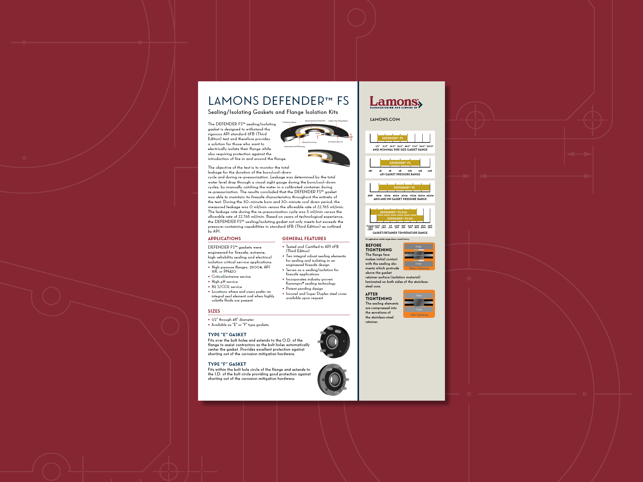
Type “E” Gasket
Fits over the bolt holes and extends to the O.D. of the flange to assist contractors as the bolt holes automatically center the gasket. Provides excellent protection against shorting out of the corrosion mitigation hardware.
Type “F” Gasket
Fits within the bolt hole circle of the flange and extends to the I.D. of the bolt circle providing good protection against shorting out of the corrosion mitigation hardware.
GASKET/RETAINER MATERIAL SPECIFICATIONS RETAINER MATERIAL (G10S6, G11S6)
- 0.3125” (7.94mm) total thickness
- Metal Core .1/4” (.250”- 6.35mm) thick – 316SS
- Laminate .032” (0.812mm) per side
Note: Consider G10S material for applications of nominal pipe size 12-inch and larger and ANSI pressure class 600# and higher.
Industries (Oil, Gas)
- Production Fields
- Petroleum Marketing Facilities
- LNG/SNG Systems
- Pipeline and Distribution Piping
- Refineries
- Tank Farms
- Offshore Platforms
DEFENDER FS™ Flange Isolation Kits
- Based on an industry proven design
- Enhanced with innovative engineered features
- Cycled tested at 10,000 psi at ambient temperature
- Made in the USA
- Tested to Shell Certification Standards
- WRAS Approved
- DNV-GL Approved
- NSF 61 Certified
Suggested Sleeve/Washer Set
FD = G10 sleeves, steel HC washers, and steel HC washers – double washer set
MFD = Mica sleeves, Mica washers, and steel HC washers
Lamons of Houston, TX requested that United Valve Inc. of Houston, Texas test and evaluate the Lamons 6” #300 class Defender FSTM gaskets pressure containing capabilities the API standard 6FB (Third Edition, Nov. 1998, Non-Bending, On-shore or Open-Offshore Test). The test involved of affixing the gasket between two flanges and fitting the flanges to United’s test setup. The gasket was then subject to burn cycle at an average flame temperature between 1400°F and 1800°F for 30 minutes while maintaining 555 psi. Upon completion of the burn, the pressure was then held during a 30-minute cool down to a temperature below 212˚ F. The gasket was depressurized and then pressurized back to 555 psi and held for an additional 5 minutes. The objective of the test was to monitor the total leakage during the duration of the burn/cool down cycle, along with the repressurization cycle with accordance to API 6FB standards. Leakage was determined by the total water level drop through a visual sight gauge during the burn/cool down cycles, and then by manually catching the water in a calibrated container during the repressurization cycle.
Test Procedure
Below is a summary of the test setup and protocol performed during the gasket fire test with accordance to API 6FB, Third Edition, Non-Bending, On-shore or Open-Offshore Test:
- Install the Defender FS™ gasket between two CS flanges.
- Bolt the flanges together using the supplied B7 studs, 2H nuts, dielectric sleeves, and coated steel washers.
- Apply nonconductive PTFE lubricant to studs/bolts and torque to 225 ft-lbs.
- Thread NPT pipe fittings into flanges and affix the flange package in the test setup.
- Connect all pressure and temperature monitoring equipment in their correct positions. This consists of two flame thermocouples, three thermocouples, and three calorimeter cubes spaced 120° apart around the circumference of the flange (respectively), and a fourth calorimeter/thermocouple cube placed furthest away from the flame sources.
- Hydrotest the assembly to 555 psi to check all fittings/connections for leaks prior to testing.
- Confirm pressure and ignite the burners under the flange assembly and start the burn cycle clock.
- Per the test protocol, the average temperature of the flame thermocouples must reach 1400°F within two minutes of ignition, and maintain an average temperature between 1400°F and 1800°F with no reading less than 1300°F until the average calorimeter temperature reaches 1200°F.
- The average temperature between the four calorimeter cubes must reach 1200°F within 15 minutes of the burner ignition.
- Conduct the burn cycle for at least 30 minutes.
- Upon completion of the burn cycle, cool the valve below 212°F.
- Depressurize the system.
- Repressurize the system to 555 psi and hold for five minutes.
- Determine the allowable leakage rates:
- AL = SD*3.41 = 7.25*3.41 = 22.765 in
- Where: AL = Allowable Leakage
- SD = Mean Gasket Seal Diameter
- Compare the actual leakage rates versus the allowable rate.